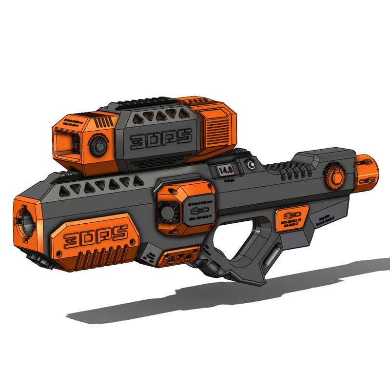
Portfolio
Rival Flywheel Project
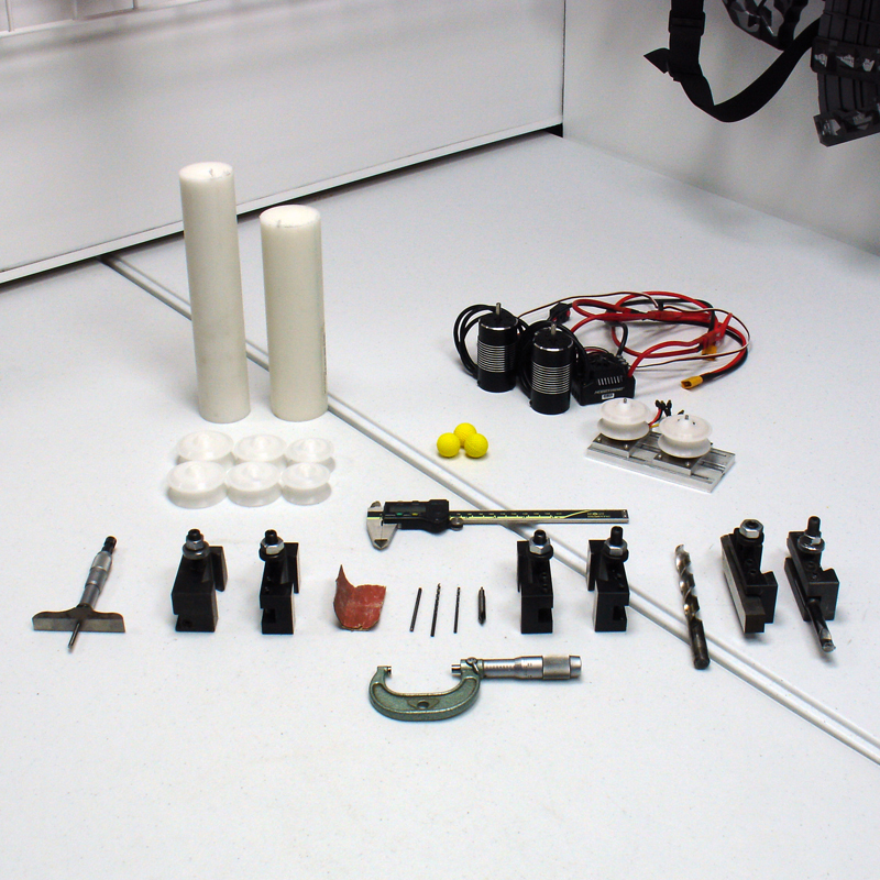
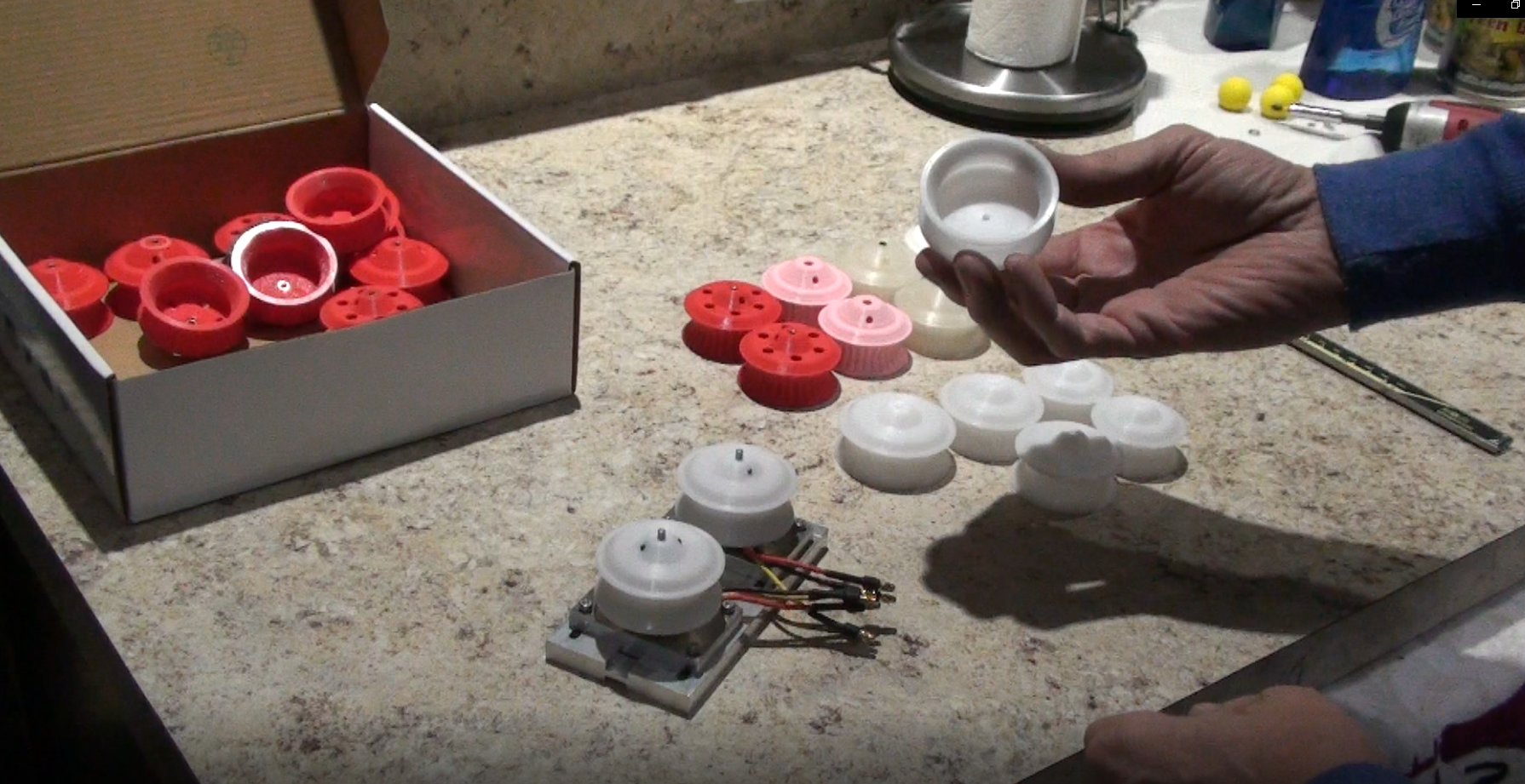
Our Rival Flywheel Project was started in late 2020 for several reasons. You see, we were working on a upgrade kit for the Perses and the stock flywheels were just not cutting it. After several experiments with the stock and 3D Printed flywheel designs, we realized that we were only going to achieve a average increase in ball speed and we are not much for just that. So of course, it turned into a mountainous project that included purchasing a 80A power supply, several amp and rpm gauges, a host of different round stock material types and sizes and a few other tools for the lathe and mill. We started by making several different testing rigs for the motors. The rigs were able to hold the motors in a simple manner and allowed us to quickly change from one motor design to another without tearing a blaster apart to do it. This also allowed us to easily adjust the distance between the flywheels (Ball Compression) something that would be very beneficial in the end. One of the main criteria we were interested in was ball speed. The variables: well just about everything we could get our hands on: Voltage/Amperage, Motor Design/Size, Flywheel Design/Size, Ball Compression, Flywheel material, etc. The Goal: balls speeds above 200 fps. However we realized that this may be hard to achieve, at least without making yellow confetti out of the balls that is. Check out this video on some of our test wheels.
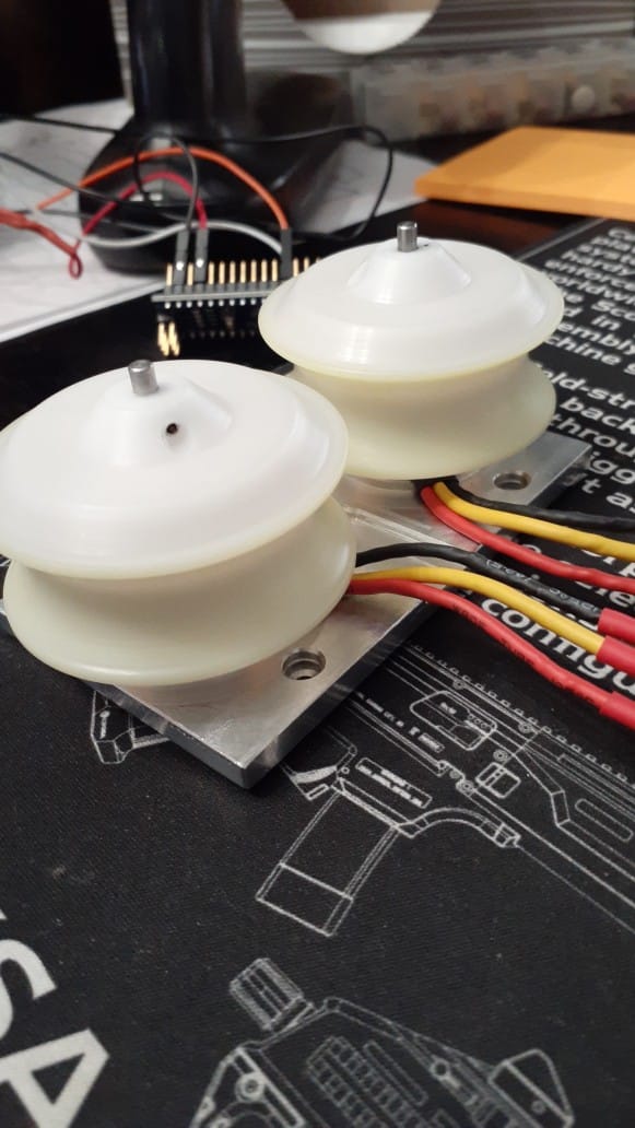
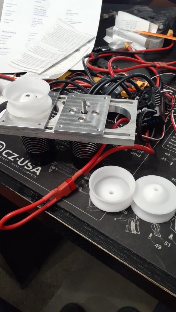
Ball speed can just about be directly related to flywheel rotation speed. Not really, but with some given dimension. Don’t forget about “slippage” an evil word when you want to go faster, faster, faster. We new we wanted high surface speed (flywheel perimeter speed) and its not to hard to figure out what is needed to accomplish that goal. We could use large diameter wheels traveling at slow to normal revolutions (RPM) or we could use small diameter wheels traveling at high to super high revs or a some sort of compromise between the two. However we know in any case that the flywheels will have to be strong, light weight, and extremely balanced, otherwise we might as well just get on the merry-go-round. Our answer, was to machine them. This is something we can do in house, relatively quickly, and we could control all the parameters needed to make a high quality part.
Now is a good time to take a break and watch the video below. It shows how we make a resin flywheel on one of our lathes. Then we will explain why this is so important.
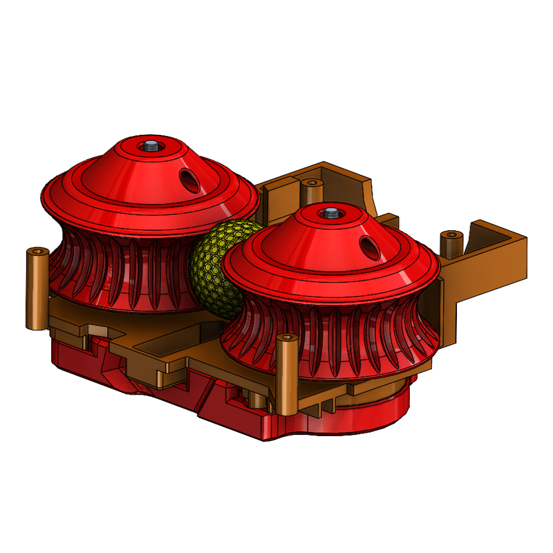
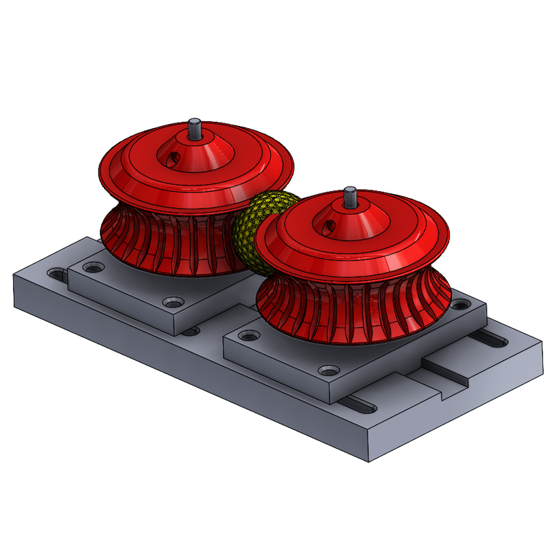
In any case, weather we want large wheels or small wheels the two things that would get started in the correct direction would be flywheel concentricity and a proper connection from the wheel to the motor shaft. So this is what we concentrated on. Different motors have different connection points, for example the stock motors in a Perses have spline shafts, where the injected molded flywheels are pressed on the motor shaft using compression to keep them on and the splines to keep them from slipping on the shaft. Most aftermarket motor do not use this method, mostly due to it inferiority to other methods. A “D” shaft is the most common amongst aftermarket motors with some just using a straight shaft. D shafts have a flat cut longitudinally along the shaft so a more positive connection can be made using a set screw(s) positioned in the flywheel itself. This greatly reduce the chance of slippage between the two. Any motor we used with a straight shaft, we took a rotary tool and abrasive wheel and ground a flat on the shaft so we could get a positive connection with a set screw. Also, it turned out that the connection point is just as important as having a balance flywheel. So much so, that we went the extra mile and use reamers to bore the shaft hole in the flywheel instead of just a drill bit. This gave us almost a press fit between the flywheel hole and the motor shaft. Best case for holing good concentricity between the two parts. Speaking of concentricity, a “true” wheel would cause much less problems than one which was injected molded or 3D printed. When you are talking about high rpm’s vibration is the enemy. Any cycling vibration would slow the wheels dramatically or much worse cause them to fly apart at high or super high rpms. These factors led us to use the methods and material we have chosen for our project. Take a look at the next video showing some very high speed (RPM) motors have a whack at a pair of our balanced flywheels.
So at the point of this posts we are actively in the middle of testing different wheel and motor designs. It will take us some time to complete the project or at least get to the point where we are comfortable with it. So the task for a better flywheel motor combination will continue. Check back again for a update on the progress. To leave you, here is a quick video of some ball velocity testing.